Analysis of TE10 Mode Propagation: Air-Filled vs. Dielectrically-Filled (Alumina) Waveguide
Project Completion Date: November 9, 2025
Download Full Report (PDF)Domain
High-Frequency (RF) Engineering, Microwave Theory, Electromagnetics
Skills Implemented
HFSS Simulation, 3D EM Modeling, S-Parameter Analysis, Cutoff Frequency Calculation
Software Used
ANSYS Electronics (HFSS)
Objective
The goal was to conduct a quantitative comparison of $TE_{10}$ mode propagation in a standard WR-90 waveguide vs. one 100% filled with 96% Alumina. This analysis aimed to validate electromagnetic theory and quantify the trade-offs of dielectric loading for RF applications.
Project Milestones
- Modeled and validated both air-filled and alumina-filled configurations against their theoretical formulas.
- Determined and compared the $TE_{10}$ cutoff frequency for each guide.
- Visualized and analyzed the E-field and H-field concentration differences.
- Compared the guided wavelength at 10 GHz.
- Quantified the insertion loss (attenuation) from the alumina's loss tangent.
Results (Simulation Gallery)
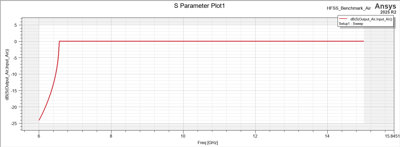
Air-Filled Waveguide Results
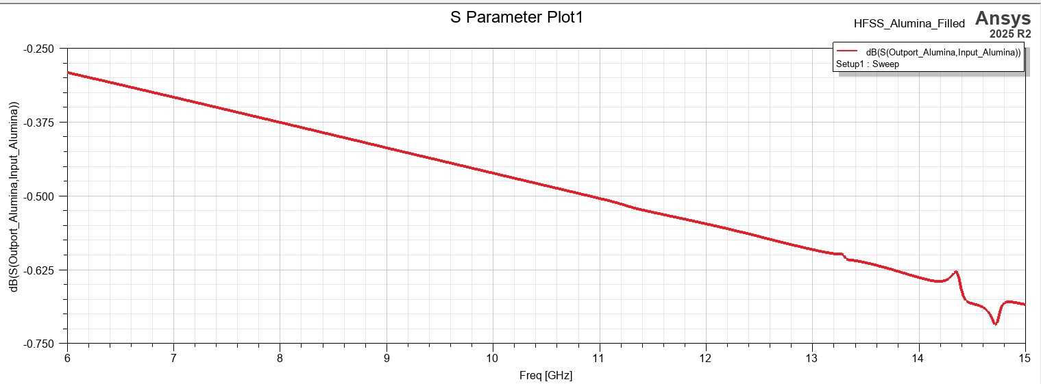
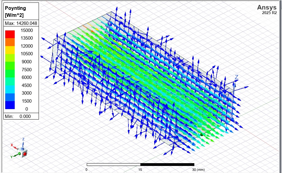
Dielectrically-Filled (Alumina) Results
Conclusion
This study successfully met all project milestones. The key findings are:
- Cutoff Frequency: Alumina drastically lowered the cutoff frequency from 6.56 GHz to 2.19 GHz.
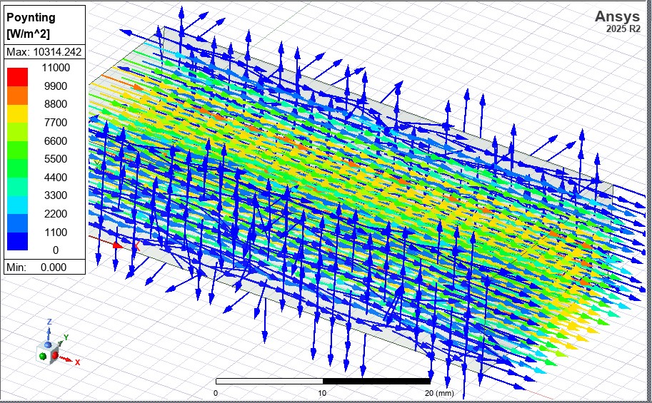
- Field Concentration: Fields were highly concentrated within the high-permittivity alumina.
- Insertion Loss: Dielectric loss was clearly quantified, showing a loss of ~0.26 dB to ~0.72 dB using Alumina.
Future Work
A logical next step would be to investigate a **partially-filled waveguide**. Such a study would involve simulating the guide with a dielectric slab of varying thickness to find a "sweet spot" for miniaturization vs. insertion loss.